How To - Martinez Brushless Gimbal Controller Set-Up
| |
Please note - The author claims no affiliation with any commercial business or entity found in this article. All ideas, processes or methods explained or outlined here are based entirely on the authors experience.
Questions? Please contact the Wiki administrator for more information. |
Contents
|
|
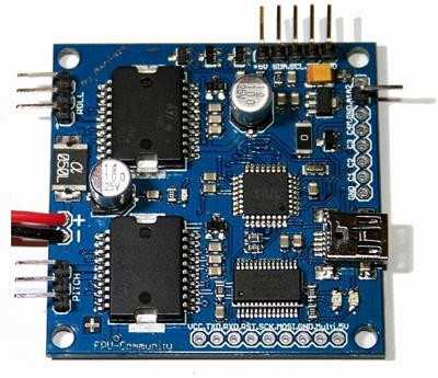
| The V3 Martinez Board |
Introduction
This article is a compilation of the information necessary to successfully set-up the Martinez Brushless Gimbal Controller. Many people on RCGroups have contributed to this article through their questions and their written experiences and for this I would say, Thanks!
Scope
The scope of this article covers basic set-up information gathered using Martinez V3 and RCTimer V1 gimbal controllers equipped with an FTDI driver chip and using a Win7 PC. It also covers set-up and tuning of the SBGC v1.0 board when the BruGi firmware is used.
Assumptions
For the purpose of clarity the following assumptions apply to all sections of this article. I will add to this list as questions of clarity come up from readers.
- 1. All stated directions with regards to rotation like "roll right" or "roll left" assume the viewpoint is through the lens of the camera or from the point of view of an FPV pilot.
Set-Up Outline
The following steps outline the high level tasks needed to insure a successful gimbal set-up. It is important to follow these steps in the order listed to minimize issues which result from "jumping ahead". It would be a good idea to read completely through this Wiki set-up article before proceeding as well.
- 1. Make sure you have the correct drivers installed and that you can successfully connect to the control board. A successful connection can be seen by observing changes made in the GUI in real time.
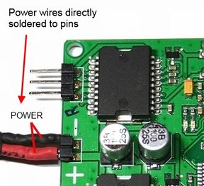
- 2. If the control board came with header pins soldered on the battery power input, it is highly recommended you solder a pigtail with a JST battery connector so that you do not accidentally plug the power in with the polarity reversed.
- 3. If not already done, flash the firmware on the board with only the IMU connected (no motors). You do not need battery power for this.
- 4. Build out all the mechanical components of your gimbal and make sure all motion is smooth and unrestricted. Do not connect motors or IMU at this point.
- 5. Mount the IMU in the correct orientation with either high quality servo tape, hot glue or screws (preferred). Never use hook & loop (velcro) or thick foam tape.
- 6. Braid the IMU and Motor wires if they are made from separate wire strands.
- 7. Mount the camera with all accessories and/or additional video connections and straps.
- 8. Secure all wires in such a way they do not pull against the gimbal motion. Do not route IMU wires together with any motor wires.
- 9. Balance the gimbal so that no matter what position you put the camera in the gimbal stays there. If it moves a small amount because of motor magnets (cogging), that's OK. If it "falls over" in any direction, it is not balanced well enough.
- a. Pitch requires the camera position be adjusted both fore-aft and vertically. It is OK to add small amounts of weight for this.
- b. Roll requires the camera position to be adjusted left-right.
- 10. Mount the control board and connect all Gimbal components. Do a final check on Gimbal motion. Pitch should be free to move +/- 90 degrees, Roll should move +/- ~50 degrees.
- 11. Connect the board to your computer and battery power in the following order:
- a. Connect battery power
- b. Connect USB
- c. Open GUI and click "Connect"
- 12. Begin tuning per the steps in the section "Controller Tuning"
Information, Software and Files
Since the Martinez board is an open source development project there are often new Firmware (FW) updates available so you will want to be able to upgrade your board. Additionally, not all boards are shipped with current (or any) firmware so you may need to upload firmware upon receiving your board.
Please download the Martinez manual and read through it carefully before starting. While it is a bit dated, it does have some good information you may need.
You can also find information on these RC Groups forum threads:
Martinez board / Open source brushless gimbal HELP THREAD
RCTIMER 2-Axis Brushless Gimbal For GoPro / CCHD
There are many more places to get information but these have served me best.
Board Identification
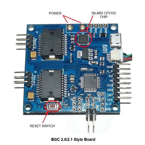
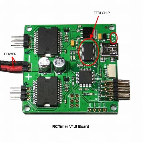
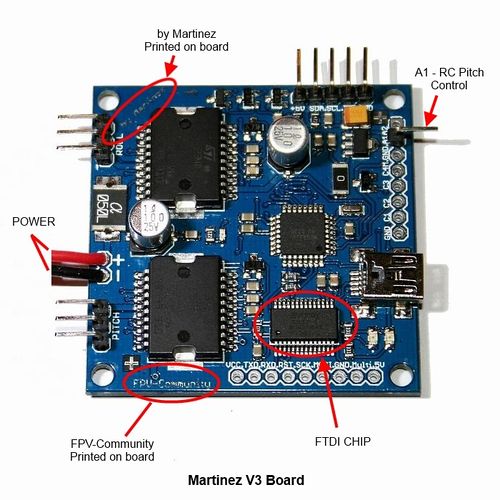
Below are three of the more common Gimbal control boards. Each one has some subtle differences but they all perform about the same.
|
This is a BGC1.0/2.0/2.1 copy of a SimpleBGC (BaseCam Electronics) design. From a component standpoint there is a difference in that this board uses a Silicone Labs (Silabs) CP2102 USB controller chip which means you must have the Pololu Silabs drivers to communicate. These boards are usually blue or black in color. In the RCGroups forums this board has been the subject of many complaints because the sellers are calling it a Martinez V3 board and providing FTDI drivers to communicate and this simply will not work. Additionally, many of these boards are coming with a "Nulled" version of the SimpleBGC software in a "Locked" state so updates and in some cases PID tuning is impossible. NOTE: If you have one of these boards, you cannot use the driver installation procedure shown on this page but the Pololu driver self installs without issues. Additionally, if the board has the "Nulled" (hacked) version of the Alexmos SimpleBGC firmare, the tunning guide also does not apply. |
|
This is the RCTimer V1 board which has been available since March 2013. It shares the components of the Martinez V3 board including the FTDI USB controller chip. In most cases this board needs the FTDI 2.8.24 Windows driver (below) to communicate. It is a well designed copy of the original V3 board and comes completely pre-soldered with all the pin-outs needed. The board color is green. |
|
This is the Martinez V3 board which is the board the open source Brushless Gimbal project is based on. Like the RCT board it is built with the FTDI USB controller chip. It too needs the 2.8.24 Windows driver and in some cases folks have posted they had to go to the 2.8.14 driver to successfully communicate. The board is distinctive with the "by Martinez" printed across one corner and "FPV Community" printed on one edge and generally do not have all the pin-outs soldered in. The color of these boards can be red, blue, black and gold. |
Inertial Measurement Unit - IMU
IMU's come in many shapes and sizes. They all use the same Invensense MPU-6050 chip and have multiple uses in many devices.

|
| Same thing only different! |
Orientation and Mounting
Orientation
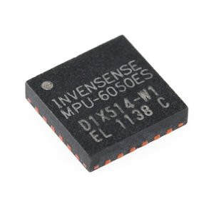
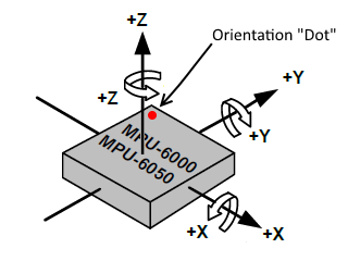
Most IMU boards have the positive 'X' and 'Y' direction arrows printed on the board. If these arrows are not printed on the board, use the following directional map to orient the board. The chip has a dimple on one corner which is used to set these directions.
|
|
| MPU-6050 Chip | Orientation Map |
|
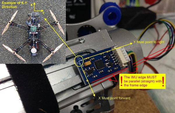
| Example using default BruGi values |
The standard orientations for a BruGi controller IMU is shown below. Positive 'Z' direction is the component side of the board so if positive 'Z' is down, the components face down. You can swap the X-Y directions and the Positive Z direction in the BruGi GUI to give you more mounting options.
- Standard -
- 'X' Forward
- 'Y' Right
- 'Z' Down
- Swap X-Y -
- 'X' Right
- 'Y' Forward
- 'Z' Down
- Swap Z (only) -
- 'X' Forward
- 'Y' Left (check reverse motor in Pitch tab)
- 'Z' Up
- Swap X-Y & Z -
- 'X' Left
- 'Y' Forward
- 'Z' Up
Vertical Mounting
If you want to mount the IMU vertically (on the back of the camera), as of this writing, you will need to change code in the Arduino IMU sketch (IMU.ino), compile and reload the firmware. The following links to a page which covers the sketch changes needed for the eight possible IMU orientations when mounted on the back of the camera:
BruGi Verticle IMU Orientation Set-up
For a PDF version of the Sketch change worksheet use this link to download:
Mounting
Fastening method is critical to the success of smooth gimbal operation. The following lists the most to least successful mounting methods:
Fastening Method
- Screw mount- This is the recommended method. Make sure to use plastic spacers or stand-offs when mounting to a metal frame.
- Hot Glue - OK but makes it difficult to remove.
- Servo Tape - OK providing it is high quality thin tape.
- Double Sided Foam Tape - Not recommended. This type of tape can amplify vibration.
- Velcro - Never use velcro to mount an IMU. It will be impossible to tune the gimbal if the IMU is mounted this way.
NOTE: It is very important that the IMU positive directions be perfectly parallel to the motor axis. On most gimbals this means the edge of the IMU board is exactly parallel to an edge of the gimbal frame. Do not mount the IMU on the camera unless the camera itself is perfectly aligned with the motor axis and can not move (rare).
IMU Wire Routing - IMPORTANT
The problems which can be caused by messy wiring and/or bad IMU connections are many so tidy wiring is important!
The things to avoid are:
- Wires which are not braided, twisted or bundled tightly together
- Wires which pass too close to a motor or with motor wiring
- Improper or loose connections
- Wires which pull against gimbal motion
- Wires which are too heavy and put a weight on Gimbal motion
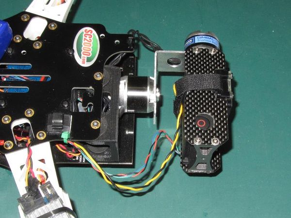
So, braid or bundle those wires! There is a catch of course and that is if your wires are too big or too stiff to braid then you will have to bundle them to keep them flexible. Here is an example using braided 30ga IMU wires on my TBS Disco:
|
| Braided silicone IMU and Camera wires |
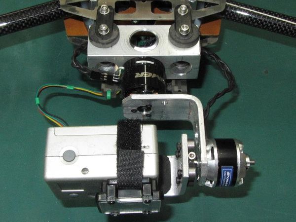
If your wires are too stiff to braid then you can bundle them together with a few short pieces of shrink tube as I did on my HT-PB quad:
|
| Bundled IMU wires |
Good things to practice here:
- Remove any connector from the IMU and solder directly to the IMU. Cover the solder joint with liquid electrical tape or hot glue
- Keep the wires in a long enough loop such that it will not interfere or pull on the gimbal motion
- Do not route IMU wires together with any motor wires
- Keep the IMU wires from passing over or too close to the roll motor to avoid the switching magnetic field there
- If you make your own harness, use 28ga or 30ga silicone wire
Board Power
For the boards discussed in this article, the power provided can be 7.4v to 14.8v (2S - 4S). I have seen one vendor claim 6S was allowable but this is not the case so be careful!
The Connection
Some of the boards come with a pair of pins already soldered in that will fit a standard servo or JST type connector. My recommendation is to NOT use this. There have been many people posting on the forums that they have inadvertently plugged the battery in the wrong way and "fried something". This generally means a new board although some have had success repairing them. To alleviate these issues, buy or make a pigtail utilizing a JST battery connector and solder this directly to the pins with a shrink tube covering.
The Source
The power source can be either the aircraft flight battery (2S - 4S only), a separate battery or a decent quality voltage regulator (VR). Each choice has some differences:
- Flight Battery - the performance will constantly change with the charge state and voltage changes your flight battery delivers. There can be a large amount of electrical noise present depending on the ESC types used and this can be very frustrating. If using this source it is best to do so with an LC filter between the board and the source.
- Separate Battery - this will give much more consistent performance results because the voltage remains relatively constant (although decreasing slightly) throughout the entire flight. A 600mah - 800mah, 3S pack is usually more than enough for several flights and doesn't add too much weight.
- Voltage Regulator - the VR is the best option with respect to overall tuning and performance providing the VR used is of sufficient power and quality. The power capacity should be better than 10 watts and if it is a switch type regulator the noise (ripple) should be below 25mv.
- Flight Battery - the performance will constantly change with the charge state and voltage changes your flight battery delivers. There can be a large amount of electrical noise present depending on the ESC types used and this can be very frustrating. If using this source it is best to do so with an LC filter between the board and the source.
In my case I use a Dimension Engineering 25 watt adjustable VR. This unit provides more than enough power for consistent performance and it is very quiet and light (10gr). I set the voltage to 9.0v and run it from either a 3S or 4S flight battery.
Driver Updates - Windows Method
This How-To is assuming you have a Windows PC. To be successful your PC will need the correct FTDI driver installed. The driver which has worked best for my boards and set-ups is the FTDI COM driver 2.8.24.0. If you have 2.8.28.0, 2.8.30.0 or higher these likely will not work.
NOTE: Thanks to Paul who contacted me, here is a reminder - Check that the cable you are using actually works! I have run into the bad cable blues myself and nothing can be more frustrating than trying to fix a driver problem with a bad cable!! - Thanks Paul!
If for some reason 2.8.24.0 still doesn't connect you might try 2.8.14.0 which some have reported success with. Here are the links for these driver files:
2.8.24 FTDI Driver Package
2.8.14 FTDI Driver Package
To load either of these older drivers follow these steps exactly in order:
- 1. Disconnect your internet to prevent Windows from auto fetching the latest driver
- (Keep it disconnected from the internet until the board is working correctly)
- 2. Plug in your board
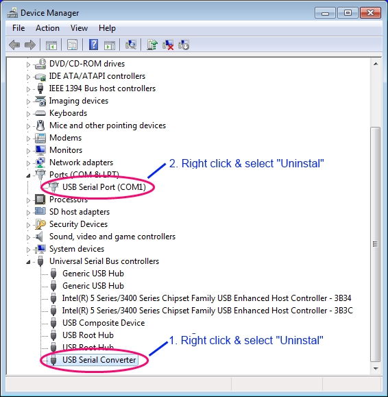
- 3. Go to device manager
- 4. Go to View and select "show all the hidden devices"
- 5. Expand "Universal Serial Bus Controllers" and "Ports (COM & LPT)"
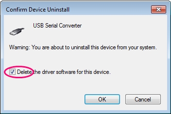
- 6. Right click "USB Serial Converter" and select "Uninstall"
- a. IMPORTANT! Also check the box "Delete the Driver software for this device"
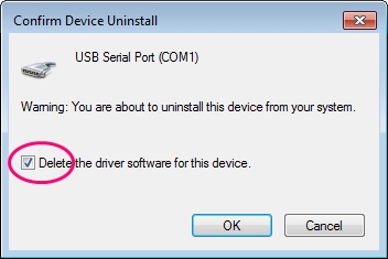
- 7. Right click "USB Serial Port (COMx)" and select "Uninstall"
- a. IMPORTANT! Also check the box "Delete the Driver software for this device"
- 8. Close all windows and re-start your system
- 9. Connect the board to USB and look for the warning that there is no driver for this device
- 10. In Device Manager, update with the driver that you have downloaded
- (On some computers you may need to reboot the system)
- 11. Plug in the board, go to Device Manager and check to see the correct driver has been installed and the COM port is a number below 9
Once you have the driver installed you are ready to begin upgrading and tuning.
Driver Clean-Up - 3rd Party Tool
Many have reported having driver issues "no matter what they try" and having experienced this myself on one of my computers I can see why. Drivers are funny things and if you are not careful they are easy to corrupt or mis-instal. Add to this Windows automation routines which constantly try and keep things up-to-date even when you may not want them to and you have a recipe for driver chaos!
On my laptop I had unsuccessfuly tried to install the 2.8.24 driver a couple of times before I realized I had to check the box to uninstall the original driver firmware (2.8.28). So, I went back, checked the box and *.24 seemed to install just fine. Then on one of my boards I could get the GUI to work but Arduino would not allow an upload. I kept getting the dreaded AVRdude error. When I checked the driver file in Windows Device Manager, it showed the correct *.24 driver and the settings were correct. This casued some serious hours of cursing and fiddling (and eventually learning :)).
In my search for "WHY" this was happening I happened on a set of free tools from Nirsoft, a company which provides free utilities (links below). Three of these utilities, DevManView, USBDeview and DriverView are awesome tools for viewing exactly what is installed in your system and for acting on the ones you want to change or delete without having to go through all the vague screens provided in Windows.
http://www.nirsoft.net/utils/usb_devices_view.html
I ecourage you to download all three of these and have a look at what you can see. I suspect you will be surprised at how many instances of some of these drivers and devices exist in your system.
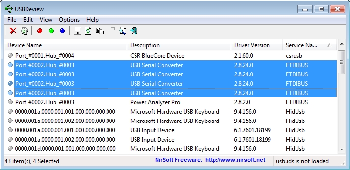
To alleviate my driver problem I used the utility "USBDeview" which shows all the USB devices Windows has a record of. I immediately saw I had multiple instances of the *.24, *.28 and *.30 FTDI drivers which didn't seem right as I thought I had uninstalled the *.28 and *.30 drivers. I also saw that when I plugged in one of my Martinez v3 boards the USBDeview tool reported it was using *.30 but Windows was reporting that it was using *.24!
To fix this using USBDeview
- Disconect from the internet!
- Open USBDeveiw using "Run as Administrator" by right clicking the USBDeview.exe file and selecting this option.
- Go to "View/Choose Columns" and de-select everything but Device name, Description, Service name, and Driver Version.
- Click the column hesding for "Service Name" to sort.
|
| A view of USBDeview |
You will now see all the FTDI drivers stacked together and you can select them as a group. Select all the *.24, *.28 and *.30 drivers, right click and uninstall them. Now, with your internet access still turned off, load the *.24 driver.
Now, go back to #8 in the section above and complete the driver instal. Done!
Firmware, Software and Apps
You will need Arduino software to upload the FW to the board. Details on how to do this can be found on the Arduino site and many other forums. The following link will take you to the Arduino download site:
Download and unzip this into a directory on your desktop or other convenient location.
Now you will need the current FW to load to your board, it can be found at the link below. The files are contained in a single download:
Download and unzip this package into the same directory that you put Arduino in. Really it can go anywhere, this is just a convenient place.
To prepare for the Arduino firmware upload:
Key Arduino settings
- Go to File/Preferences and select the folder where your new firmware files are located
- Check the box "Show verbose output..." and click "OK"
- Go to Tools/Board Type and select - Arduino Pro or Pro Mini (5V, 16 Mhz)w/ ATmega328
- Go to Tools/Programmer and select - USPasp
Board connections
For firmware uploads and sensor calibration, battery power is not required if you follow these steps (in order)
- a. Disconnect the motors
- b. Make sure you have a good connection to the IMU
- c. Connect to USB
- d. Connect to the software (GUI or Arduino)
Now in Arduino
- d. Start Arduino and select the COM port assigned to your board (from Device Manager in windows)
- i. If you are on an older software it is wise to clear the eeprom - File/Examples/EEPROM/eeprom-clear (Verify and Upload)
- e. In Arduino go to File/Open and select the *.INO file for your Firmware package, EX: _BruGi.INO
- f. Click on "Verify" (Check mark button) and when it completes click "Upload" (Arrow button)
Controller Tuning
I put this tuning guide together after much fiddling and even more forum reading and it will be updated anytime I feel there is improvement in these methods. This outlines how I get close to a final tuning solution. Note that there is generally more follow-up fine tuning needed for perfectly smooth video.
Important Things to Note
- Board Power - The Martinez boards can be powered with a 2S to 4S lipo pack. For better results, use a separate battery. For best results, use an adjustable voltage regulator set up at 9 volts.
- Gimbal Motion – It is critical that all movement of the gimbal components are completely unrestrained. That is, perfectly smooth with no resistance.
- Balance – Your gimbal, with camera installed and all cables connected must be balanced near perfectly. That is, without any power applied, if you move the camera to any position, it stays there and does not “fall over” (side to side or front to back). It may move slightly due to magnetic motor "cogging" and this is acceptable.
- Cable Routing – All motor, IMU and/or video cable routing must be free from applying any tension (pulling) on the gimbal across the full range of desired motion. It takes very little cable resistance to throw the gimbal balance off and cause bad behavior. Never route IMU cables close to motor wires or any other source of EMI as this can cause erratic behavior and errors.
- IMU Mount Method – The mounting method of the IMU board is very important. It cannot be loose or free to vibrate as this will play havoc with the sensors. The recommendation is to mount it with machine screws solidly to the top or bottom camera plate. Many people also find that high quality servo tape ([U]not[/U] standard 3M double sided foam tape) works fine as well. Never use Velcro (hook and loop).
- IMU Mounting Orientation – With the default Martinez/BruGi software settings, the IMU board (the really small one) is mounted such that the “X” arrow shown on the board component side is pointed forward and the “Y” arrow points to the right side. This means the components will be on the downside of the board. You can swap the X-Y orientation or the Z/-Z orientation in the GUI if you want to mount it differently (but still horizontally). NOTE: Not all IMU's are created equally! Some have the X/Y directions printed on them and some do not. Please see "Motor Direction" section below for more information.
- Drivers – All necessary drivers must be installed and functioning correctly. On Windows PC’s, the 2.8.24 driver is the most common working driver (see driver section above).
- Connection Sequence - For "Live" tunning, that is with motors connected, always follow this sequence:
- 1 - Connect battery power
- 2 - Connect USB
- 3 - Open GUI and click "Connect"
PWM & PID Value Definitions
PWM is a direct multiplier of the power provided to the motors by the controller from the battery. Higher 'PWM' usually means better performance especially for erratic flying and or harsh conditions but also means more heat on the motors. Having said that, this value should be no higher than what is required for stability. Always check your motors and control board for heat when tunning and lower the 'PWM' value if necessary.
- Low PWM will result in the gimbal being pushed into position by wind or other weak forces with not enough power to recover
- High PWM can result in motor heating, aggressive oscillation and controller failure
P - can be best described as torque needed to move the gimbal. Heavier cameras need more torque. This is also directly related to power as you can only provide as much torque as you have overall power to the motor. Aggressive flying also needs more 'P' to overcome inertia. More 'P' is generally needed on the Roll axis than the Pitch axis as the roll motor generally has to move more mass than the pitch motor.
- Low P can result in an inability to maintain gimbal orientation during maneuvers (flopping)
- High P can result aggressive oscillation, overheating and loud steady motor hums
I - is the motor action speed. The higher the 'I' value, the faster the motor will rotate towards the reference position (target). Keep in mind, the faster the motor is rotating the more difficult it is to stop on the target. 'I' should be no higher than necessary to maintain level. Generally Roll will have a higher relative 'I' value than Pitch.
- Low I can result in twitching especially in unbalanced setups as well as slow recovery (Horizon Drift) and slow RC control
- High I can result in high frequency oscillation, past target "overshoot" and very fast RC (tilt) control
D - handles or dampens the "bounce". Bounce is shown in the GUI trace as oscillations when bumped off target. 'D' should be as low as possible to minimize the damping affect but keep the number of bounces to 1 or 2.
- Low D can result in the gimbal overshooting during extremely fast maneuvers and oscillating on return to level
- High D can result in the gimbal being too slow when attempting to return to level and can result in rather aggressive oscillation
So to sum up, when a deviation for level is detected, the system reacts at I speed with P torque to a target where it engages a D brake.
Motor Direction - VERY IMPORTANT!
Motor direction can be difficult to understand and adjust in the BruGi set-up but it is important. Many have commented they cannot see any difference if they change the motor direction checkbox in the GUI or by reversing two motor wires. For the most part this is true if you don't know what to look for and even if you do, it still can be very difficult. This is one feature of the Alexmos system that really shines because they have provided an automatic solution in their GUI. This "AUTO" button for motor direction simply moves the gimbal in the positive X and Y direction and compares this to the response from the IMU. If there is a mis-match, it automatically reverses and saves that motor in the eeprom.
IMU Orientation Check
To see the differences you must first understand which motor direction is positive and negative. The IMU is what measures direction and angles that will show on the trace chart if your IMU is mounted correctly AND the IMU orientation is set up correctly in the GUI. The positive directions are defined as follows:
- Gimbal roll has positive rotation to the right
- Left mounted Pitch motor has positive rotation tilting back (looking up)
- Right mounted Pitch motor has a positive rotation tilting forward (looking down)
So with this information you can start the trace chart in the GUI and lightly bump the camera/gimbal to the right (positive) direction. If the chart line for roll jumps "UP" and the green numbers show a positive value, this is correct. Repeat with Pitch, bump the camera back (look up) and the orange chart line for pitch should jump up, again, positive and correct. If these values don't follow this scenario then either the IMU is positioned incorrectly and should be re-positioned or the GUI settings for orientation are incorrect. Once correct, the board is sensing the correct motor directions.
Motor Direction is where everyone seems to get a bit lost because there is very little information on what this does or means. If you consider how a simple control system might work in terms of simple If-Then logic it would look something like this:
- IF IMU senses roll right
- THEN turn roll motor left
- IF IMU senses level
- THEN STOP
- ELSE ERROR
Now, understand this is over simplified but it does illustrate two important points:
- 1. The IMU must sense direction correctly, + or -, in terms of the programmed driven motor direction.
- 2. If the feedback loop containing motor, controller and sensor are not aligned in terms of direction then the controlled action is being driven by error loops rather than direct control loops.
In other words, for the program to run smoothly and without error, sensing left must be left and rolling right must be right.
Motor Direction Check
Template:New Added August 9, 2014
I was recently given a new method for checking correct motor direction by one of the current firmware developers and poster "aloish". This method is greatly simplified and produces obvious and immediate results. Many thanks to Alois for providing this information!
NOTE 1: You need to have at least enough tuning done for the Gimbal to be stable (not shaking) for this to be successful.
NOTE 2: The method described here applies to all firmwares which have the FPV Follow and Freeze modes available. These functions were made available on all 050 firmwares. To check motor direction on earlier firmwares please go to Motor Direction Check - Early BruGi Firmware.
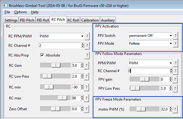
- 1. With the board powered and the GUI active change to the RC Pitch tab. In this tab you will be making changes to "FPV Activation" and "FPV Freeze Mode Parameters"
|
| RC Pitch Tab/FPV menus |
- 2. In the "FPV Freeze Mode Parameters" menu, set the value equal to or greater than the PWM value you have set for Pitch

|
| FPV Freeze Mode PWM value |
- 3. Next, go to the "FPV Activation" menu and change "FPV Mode" to Freeze

|
| FPV Mode setting |
- 4. You will now select the menu option Permanent On in the "FPV Activation" menu selection "FPV Switch" and watch how the Gimbal reacts

|
| FPV Switch setting |
- If the Gimbal has no reaction, the Pitch motor direction is correct, go to step 5
- If the Gimbal immediately drops or moves to an alternate position then the motor direction is incorrect
- To correct, go to the Pitch tab and select or de-select the "Reverse" check box and then re-test
- 5. Repeat for the Roll function
- 6. Make sure you have re-selected "Permanant Off" and save to eeprom!
To finish this off, it's a good practice after doing this to mark the motor connections so that they are always plugged in exactly the same way to the board every time.
PWM & PID Parameter Tuning
This tuning method should work on any BruGi software/board providing you understand there may be differences in the values and/or percentages.
From the BruGi project - Documentation
NOTE: Make sure you use the GUI that came with the firmware version you are using
- 1. Live tuning start-up sequence:
- a. With camera installed and balanced, connect battery power to the Gimbal
- b. Connect the USB
- c. Start the GUI and click connect
- 2. Zero out your max PWM and PID values in both Pitch and Roll
- 3. Beginning with Roll, start with a value of 5 on P, I & D (on v048, start with P=5, I=0.1, & D=5)
- 4. Raise the PWM value until the Roll motor begins to vibrate then back-off enough to completely stop the vibration
- 5. Raise the P value until the motor just begins to vibrate
- 6. Raise the D value until the motor becomes quiet
- 7. Continue going back and forth between P and D until you have reached the highest P value you can
- 8. Add the values for P and D together and divide by 2 to get a starting value for I (049 and up firmware, for 048, change I to 0.5)
- 9. Give the gimbal a light tap on one side while watching the GUI trace to make sure it immediately recovers
- a. If it starts to hum or takes a long time to settle down, I is too high, reduce by 10%
- b. If it returns immediately turn I up by 10% and recheck. The goal is the highest value of I without causing it to vibrate after a "tap"
- 10. Roll Tuning should be complete! Calibrate the Gyro and save these settings to your gimbal. THIS IS VERY IMPORTANT. If you are on firmware r161 or lower follow these 2 steps:
- Click on the options tab and then click "Save to Board"
- Click on options tab and then click "Save to Flash".
- If you are on a newer firmware than r161, simply click on options and "Save to flash".
- 11. Now, go to Pitch settings and repeat steps 3 through 10.
Time for a test flight!
Make sure you write down your final settings each time you tune as you may have to go back and make adjustments for balance or equipment changes.
Version Settings
The following are examples of settings I have used in various versions of the firmware. (Rounded to the nearest whole number)

|
A Note on Board Operation LED's
There have been many instances where the LED lights do "funny things". I don't claim to know precisely what they mean as there are different LED configurations on different boards. Here is a quote I found on the subject direct out of one of the SBGC manuals and it primarily refers to the SBGC architecture.
There are 2 LEDs onboard. Red led lights when power is connected. Green/blue LED signals actual state of the system:
 * LED is off — pause before calibration, to take hands off or to level gimbal.
 * LED blinks slowly – Calibration in action. Freeze gimbal during this process.
 * LED blinks fast — system error, stabilization cannot be performed. To check error description,connect to GUI.
 * LED is on — normal operation mode.
 * LED is on, but blinks irregularly – I2C errors appears.
I suspect there may have been a change in the v050 BruGi firmware because many have reported a blinking blue LED when updating to this version so it may have something to do with the new battery monitor. I would say in any case that if it works, ignore it :)
Troubleshooting
The following is a short list of some common issues with remedies to try if you find yourself having one:
- avrdude: stk500_getsync(): not in sync error
- This is generally caused by a communication problem between the BruGi control board and your PC. The most common cause is an incorrect FTDI driver or an incorrect installation. Please read through the driver section above.
- The gimbal only works when the USB is plugged in
- This means either the board is bad or someone has inadvertantly plugged the battery in with the polarity reversed which will burn a trace or a fuse. Fix or replace the board.
- I can't get the gimbal to settle down enough to tune
- This happens when the initial tuning parameters (PID's) are too aggressive for the gimbal components. For initial tuning, start with the motors disconnected. Set the starting parameters for one axis and set the others at 0. Now with the motors still disconnected, level the gimbal and run the Gyro and ACC calibrations. Go to the tuning section in this article and begin tuning.
- Pitch and/or Roll is erratic
- In all cases erratic behavior can be caused by electrical noise and vibration. Make sure the IMU wires are not routed near or against any motor or motor wires. Braid the motor and IMU wires if they are made from separate strands. To check if vibration is a cause take some video with motors off and see if the erratic behaviour still exists. Make sure all props are balanced and consider balancing the motors.
- Pitch is very difficult to tune because there is very little mass to dampen the motion. Gimbal balancing is critical to a smooth response so the first thing to check is the fore-aft and verticle balance of the gimbal. Another common reason is IMU wires interfering or pulling on the gimbal frame. Make sure there is no interference or tension against gimbal motion through the full, expected travel.
- Pitch is very difficult to tune because there is very little mass to dampen the motion. Gimbal balancing is critical to a smooth response so the first thing to check is the fore-aft and verticle balance of the gimbal. Another common reason is IMU wires interfering or pulling on the gimbal frame. Make sure there is no interference or tension against gimbal motion through the full, expected travel.
- Roll is also affected by the same outside influences as Pitch so check right-left balance and (again) make sure there is no wire tension pulling on the gimbal.
- Roll is also affected by the same outside influences as Pitch so check right-left balance and (again) make sure there is no wire tension pulling on the gimbal.
- Horizon or Roll Drifts
- Horizon drift happens because the gimbal is not tuned well enough to keep up with the changes in gimbal frame angles. The most common cures for this are:
- 1. Raise the Roll 'I' value - this increases motor speed to help keep up.
- 1. Raise the Roll 'I' value - this increases motor speed to help keep up.
- 2. Roll motor is reversed - the easiest way to check for this is to go in the GUI select or de-select the motor reverse check box and test fly it. You should also read the section above on Motor Direction.
- 2. Roll motor is reversed - the easiest way to check for this is to go in the GUI select or de-select the motor reverse check box and test fly it. You should also read the section above on Motor Direction.
- 3. Raise the PWM value and tune out any vibration, keep 'I' as high as you can.
- 3. Raise the PWM value and tune out any vibration, keep 'I' as high as you can.
- Gimbal works OK but then "Freaks Out"
- This scenario has two main causes:
- 1. Bad or intermittent connection to the IMU. This ususlly occurs when the IMU board has a JST-SH connector which has become loose. If possible, solder the wires to the board.
- 1. Bad or intermittent connection to the IMU. This ususlly occurs when the IMU board has a JST-SH connector which has become loose. If possible, solder the wires to the board.
- 2. Wire tension or poor balancing. If there is wire tension against the gimbal motion which doesn't happen until near extreme movement this will cause the issue. Balancing issues are similar.
- 2. Wire tension or poor balancing. If there is wire tension against the gimbal motion which doesn't happen until near extreme movement this will cause the issue. Balancing issues are similar.
- Gimbal works OK but then locks-up (freezes) or shuts down
- Lock-ups and shut downs are generally caused by too much control system error. That is, some thing has driven the gimbal so far out of its operating envelope it cannot resolve the problem. Very often this is caused by improper tuning, incorrect motor direction selected or high vibration affecting the IMU sensor.
See Also
- Brushless Gimbal Project
- Easy Brushless Gimbal
- RC Groups Martinez Thread
- RC Groups RCTimer BruGi Thread
Vendors used for this Project
