Strix StratoSurfer Motor Mount Design Study
Introduction
This page is written to support my findings with regards to modifying the motor mount structure and durability on the Strix Stratosurfer. This applies to motor mounts which have been modified with an offset mount plate to gain clearance for a larger prop and motor. In no way should this write-up be construed as a negative comment or complaint about this excellent model.
Design
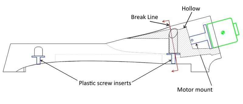
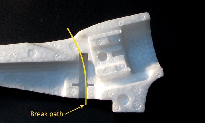
The stock mount has very little foam in cross section to support the plastic mount pieces and the motor so any additional weight or leverage will put this foam piece under enormous stress. Below are some general sketches and some photos of an un-assembled stock foam mount to illustrate where weakness shows up when modifying the mount for a larger motor/prop.
|
| Cross section showing where the mount might fail with an offset plate mount |
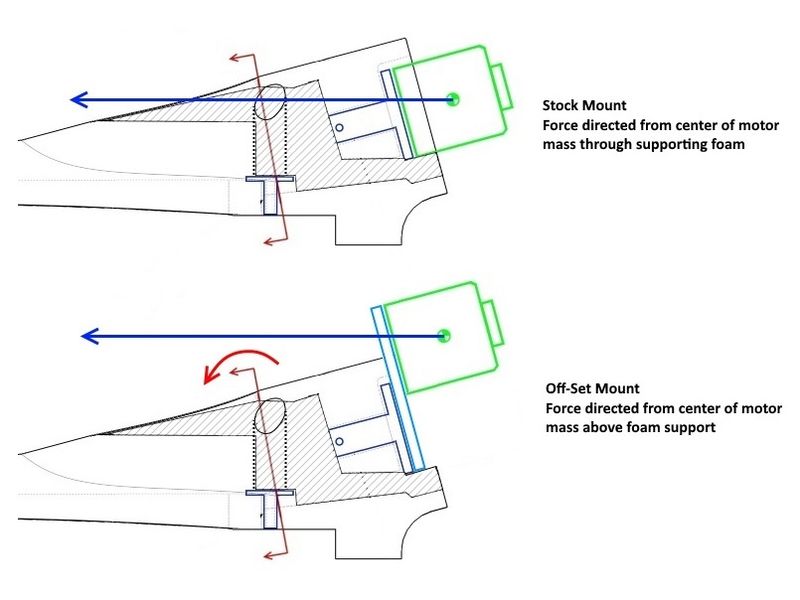
Below you can see the difference in how load forces are applied with a hard landing or sudden stop of the airplane. In the top view of the stock configuration, the applied force goes through the mount foam compressing it but not creating a serious bending moment. In the bottom sketch you can see that by raising the motor via an offset plate, the applied force line is well above the supporting foam structure creating a serious bending moment around the weakest part of the mount.
|
| Application of forward forces on landing |
Typical Failure
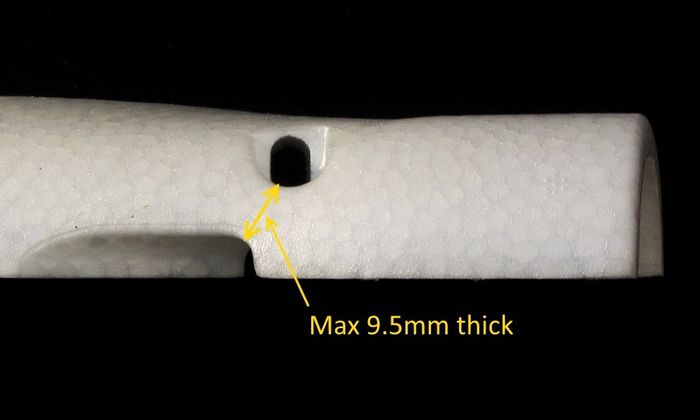
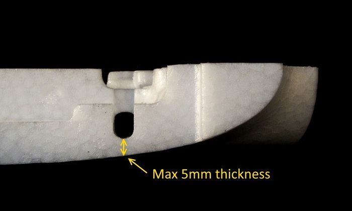
The photos below show where the foam will "tear" and an actual failed mount.
|
|
|
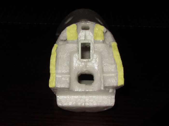
Below is a picture of a failed mount showing how small the area of foam support is. The area highlighted in yellow is all that supports the motor and the motors center of mass is above the weakest part of this support putting it in an extreme stress condition anytime the plane comes to a fast stop.
|
See Also
Comments? Questions?