How To - Make Your Own G10 Parts
| |
| The Project |
Introduction
This How-To is all about a simple way to make fairly accurate parts you would otherwise have someone make for you on a CNC router or laser cutting machine. It is a simple method utilizing basic tools and requires only a little extra time. To illustrate this I will make a small G10 Fiberglass part for a simple gimbal project I am working on
What you need
The following lists the basic tools you will need to do this:
- Drill (Drill Press is an advantage)
- Drill bits
- Counter sink bit
- Bench vise
- Center punch and light hammer
- Sanding block
- Xacto knife
- Computer & printer
Step 1 - The Layout
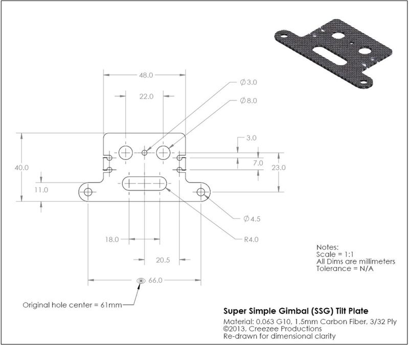
One of the most time consuming parts of any project is the planning and this is no different. For this project we can speed this up and make the results more accurate by using a CAD or drawing program to do the layout work.
If you already have a CAD tool, great! If not, you can get a free copy of DraftSight, a 2D drawing platform from the makers of SolidWorks. This is a very robust 2D drawing platform so if you have never used a CAD system before, plan on spending some time learning how to get started. The good news here is A-you will learn something valuable and B-You could always use this new found skill to send prints to a CNC or Laser operator.
To get a copy of DraftSight go to this link, scroll down and click on "Free Download"
http://www.3ds.com/products-services/draftsight/overview/
I won't go into any instruction on using a CAD package here, I'll leave that up to you and jump ahead to the layout I have done for my little project.
Once you have finished the layout you have to get it onto the piece of material accurately so you can begin the procces of drilling and cutting. Normally this is where a little project like this can get very time consuming but I have found a simple way. To do this quickly, I simply print the layout on an adhesive backed shipping label then stick the label to the material and begin cutting!
What's the Catch?
While this sounds easy, it can be a little tricky if you don't have the ability to print your layout to a perfect 1:1 scale. There are many ways to do this and the simplest way I have found is to use Adobe PDF documents as they print at 100% perfectly. So, from your CAD program, if you can save as PDF you are in business, If not, see if you can find a file converter or PDF print driver to force it in to this format.
Step 2 - Drilling and Cutting
OK, so I have created the layout, moved it in the CAD program so it will center on a label when printed and printed it (I use a semi-transparent label material). I now trim the label and stick it on the material:

|
| Trimmed layout on the material |
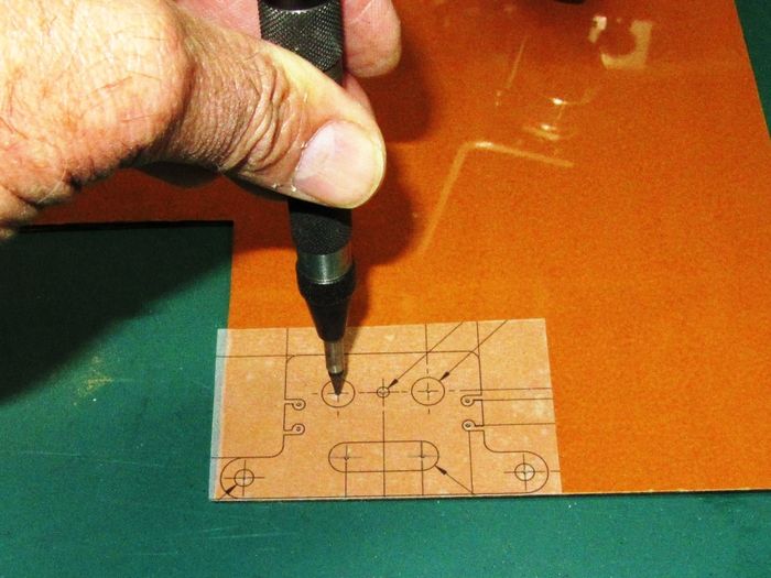
Next up, mark the material with a punch on all the hole centers. For this I am using an automatic, spring loaded center punch (about $6 at Harbor Freight). If you use a standard punch and a hammer, BE CAREFUL!
|
| Punching the hole centers |
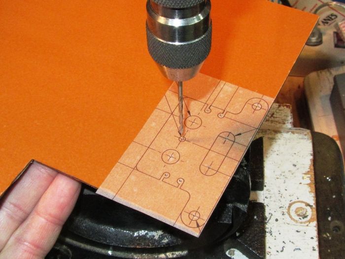
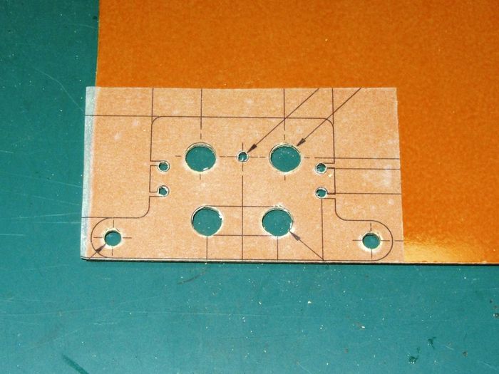
With the center marks you can now start drilling. This is best done by first drilling all the centers with a very small drill bit like a 1/16" or 1.5mm. After getting this done, then use the proper size bit to finish the hole. Drill very slowly through the material or you may shatter or tear the back side and always use a sharp bit.
|
| Pre drill the centers |
|
| Drilling complete! |
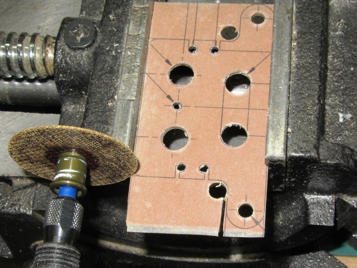
Finish rough cutting the material using a saw or Dremmel. For cutting G10 or CF sheet, use a thin steel cut-off wheel which will go through these materials like butter.
|
| Rough out the profile |
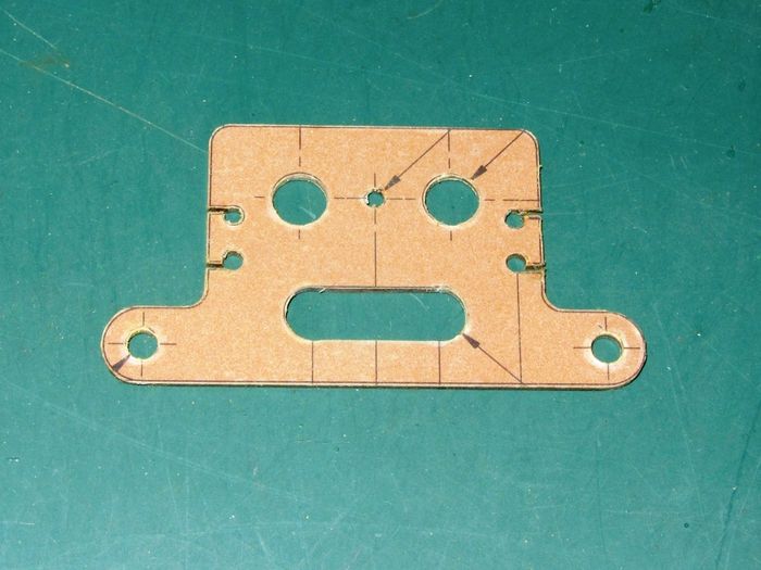
Last - Clean-up!, clean up the holes with a sharp Xacto knife and the counter sink bit, sand all the straight edges to the lines and round all the corners with the sanding block.
|
| Clean-up time |
|
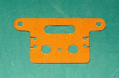
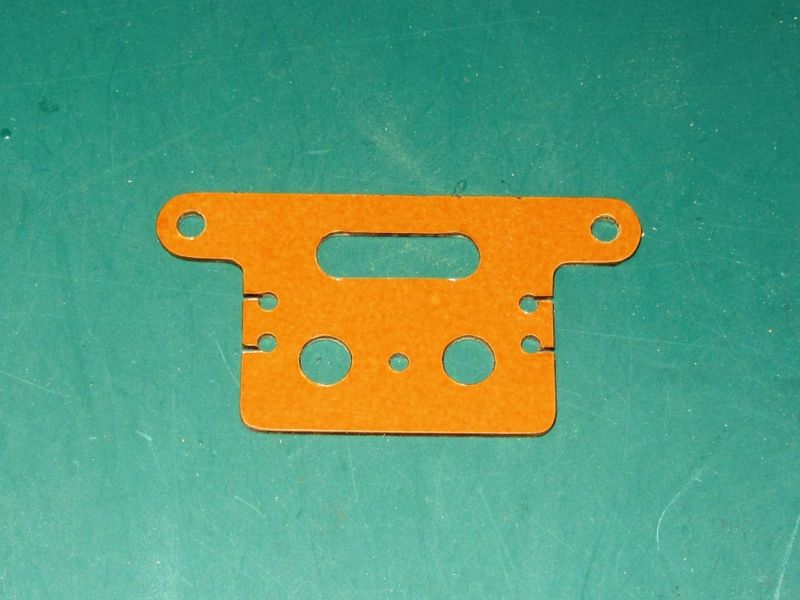
| A completed part! |
See Also
Vendors used for this project
Comments? Questions?
