How To - DragonLink MicroRX Channel Assignments
From ItsQv
| |
Please note - The author claims no affiliation with any commercial business or entity found in this article. All ideas, processes or methods explained or outlined here are based entirely on the authors experience.
Questions? Please contact the Wiki administrator for more information. |

| |
| MicroRX! |
Channel Assignment Process
These are the steps to follow to get your DragonLink MicroRX output pins to work with channels 9-12 in PPM mode. Assumptions are that you already have the DragonLink software, the system is working and you just want to add a channel or two for some other functions like a gimbal controller or camera switch.
- 1. Set-up the your flight radio to output at least 12 PPM channels and assign a switch to at least one channel (or more) above channel 8.
- NOTE: Some radios require a manual reset of the frame length to operate above 8 channels so if you you get errors, find this parameter in your radios menu set and make changes according to the following table.
- Normal Frame Lengths:
- 8 Channel - 22.5ms
- 9 Channel - 24.5ms
- 10 Channel - 26.5ms
- 11 Channel - 28.5ms
- 12 Channel - 30.5ms
- NOTE: Some radios require a manual reset of the frame length to operate above 8 channels so if you you get errors, find this parameter in your radios menu set and make changes according to the following table.
- 2. Plug the MicroRX into your computer using a micro USB cable and open the DragonLink RX GUI software.
- 3. In the GUI, check that the drop down for "PPM Channels" is set to 12.

|
| Set to 12 channels |
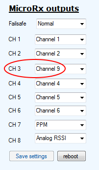
- 4. On the MicroRX Outputs, select an output pin and change the channel to the one (or more) you created in your flight radio.

|
| New channel assignment example |
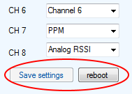
- 5. At the bottom of the list, click on "Save Settings" and "Reboot".

|
| SAVE changes! |
- 6. Power down the RX and the TX and follow the BIND process below.
Binding Process
First a little info on the RX LED's
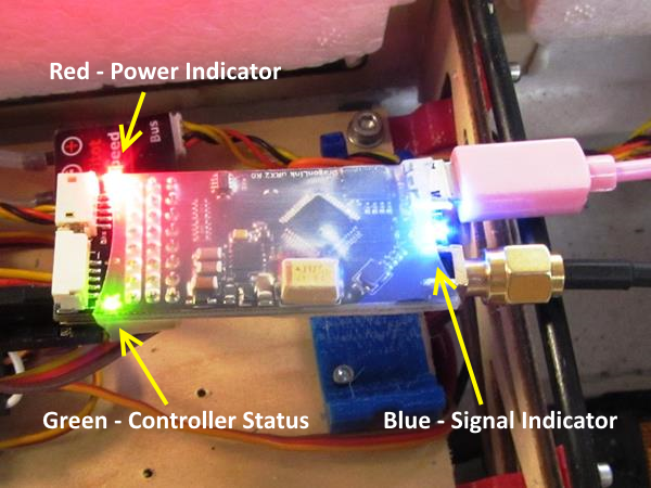
- RED - When On, the red LED indicates there is sufficient power to operate the RX
- GREEN - The green LED is the status of the controller chip
- In binding mode - Flashing Green = Valid Bind
- Operational - Solid Green
- Blue - The blue LED is the RF signal indicator.
- RX Bound with Solid Blue = Full Signal
- RX Bound but Flashing Blue = Lost Packets (The more packets lost the more this LED tends to be Off)
- RX Not Bound Dark = Zero Signal (no packets)

|
| LED Labels |
- 1. Start with both the DragonLink TX and RX powered off.
- 2. Press and hold the BIND button on the DragonLink TX.
- 3. While holding the button, turn the DragonLink TX on.
- 4. Wait until the TX LED turns ORANGE (some may be yellow), then release the button.
- 5. The DragonLink TX LED should now be flashing Orange (or yellow) rapidly. If it isn’t, restart the process from step 1.
- 6. Power on the DragonLink RX.
- 7. The DragonLink RX’s Red Power Indicator LED will be solid and the Green Status LED will be flashing.
- 8. Power cycle the DragonLink TX.
- 9. After the DragonLink TX comes on, wait for the TX LED to change to solid Green, the RX lights will not change at this point still showing Solid Red and Flashing Green.
- 10. Power cycle the DragonLink RX.
- 11. Now you should see all three LED's, RED, GREEN and BLUE on and solid.
You will note in the RX GUI, the pin outputs you have assigned new channels to will not move with the original stick inputs. They will now move instead with the new channel assignments.
- THIS IS OK Only the receiver PINS have been re-assigned, the PPM channel stream has not been changed so the original channel 3 function, from the example above, will still work as before.
Power up your plane and check all functions, they should be operational as before as well as the new PPM channel functions.
See Also/Downloads
Comments? Questions?