Heavy Duty Pan and Tilt
| |
This page or section is under construction and will change going forward.
Questions or Comments? Please contact the Wiki administrator |
Contents |
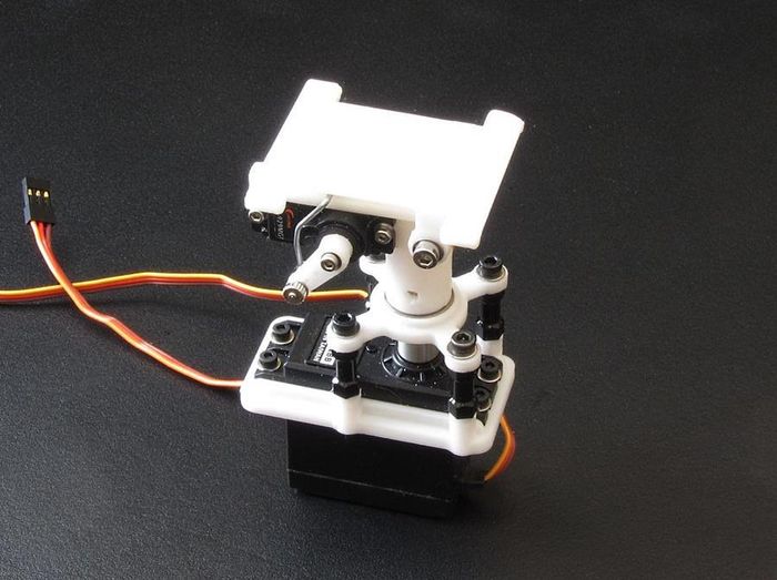
|
| Mounted on my big Talon |
Introduction
After buying and building several Pan and Tilt set-ups I got tired of how cheaply the purchased ones were and how flimsy they all were. The biggest problem has alwys been the pan axis is simply never robust enough.
When I decided to put together a pan set-up for my big Talon to carry a 2 axis brushless gimbal, I went looking for components that I could buy to build a stout pan mechanism and I found the components in a company called Actobotics.
With their servo coupler and bearing plate I was able to build on a 3D printed servo mount, a raised bearing that made the servo connection very strong. This structure kept all the pressure off the servo shaft and its bearings.
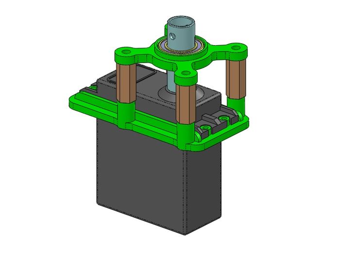
|
| Base unit showing Coupler and Bearing plate |
I've added to this a turret and tilt mechanism which I have modified many times.
Tilt Configurations
Because I always seem to need something different for every plane I've ended up with several versions of this idea. Most of my planes only require the ability to look down and around so there are three different camera mount plates.
- Standard Modius/Runcam mount
- Dual Camera Mounted
- Misc Camera mount
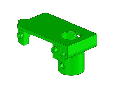
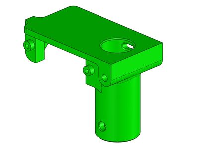
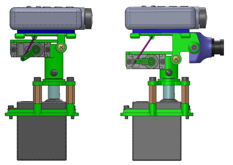
Added to this I have made two different height turrets, one for the three mounts above and one for a tilt which looks both up (19 deg) and down (-42 deg). This one also has a over-under camera mount for a Mobius/Runcam and an HS1177 camera. This one should work well in a head tracking set-up.
|
| Short and Tall Turrets |
|
| Range of Motion 0 to 70 Degrees Range of Motion -20(up) to 42(down) Degrees |
| Single and Dual Camera set-ups |
Deck Mount Configurations
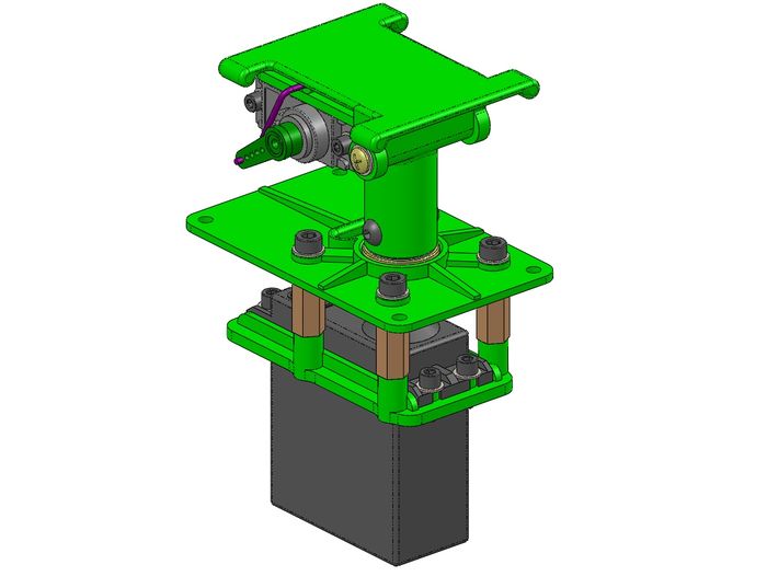
I designed three different ways to mount it to a deck. The first deck plate which incorporates the bearing mount puts most of the unit below the deck.
|
| With top deck-mount plate |
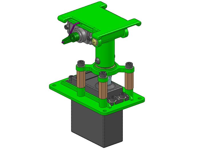
The second deck plate replaces the servo mount and puts the tilt mechanism up higher. This would be used when you don't have a lot of depth under the deck.
|
| With lower deck-mount plate |
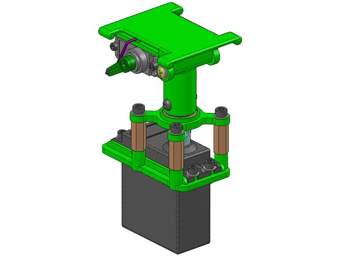
The last method is to simply drill the airframes deck to fit around the standard servo bracket.
|
| With no deck-mount plate |
Parts and Specifications
Parts
Bottom Unit Printed Parts
- Std Servo Bracket
- Servo Bracket/Deck Plate
- Bearing Plate
- Bearing Plate/Deck Plate
Top Unit Printed Parts
- Tall Turret
- Short Turret
- Mobius Mount
- Dual Camera Mount
- Misc Camera Mount
- Over-Under Camera Mount
Servos
- Pan - GWS S125-1T (25 tooth)
- Tilt - 9g/120 Degree servo
Hardware
- 2x M3 x 20mm Nylon PHS
- 4x M3 x 8mm SHCS
- 6x M3 Flat Washer
- 4x M2.5 x 8mm SHCS
- 4x M2.5 Flat Washer
- 4x M2 x 6mm SHCS
- 4x M2 Flat Washer
- 4x M3 x 15mm Aluminum Stand-offs
- 1x Actobotics Servo Coupler - 25 tooth
- 1x 0.375"ID x 0.625"OD x 0.156"L Ball Bearing
- 3" 0.047" Steel Wire
Weights and Measures
- Total weight with all hardware and a true 9g tilt servo - 93grams
- Pan rotaion - 385 degrees
- Tilt range, single camera - 0-70 degrees (down)
- Tilt range, dual camera - -19 (up) to 45 degrees (down)
Parts Preparation
On any 3D print project, part preparation is key to a successful completion. The following images show what work needs to be done for this success.
Servo Plate/Lower Deck Mount
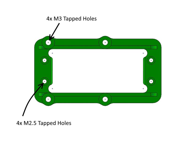
The servo mount needs 4 holes tapped to M3 and 4 holes tapped to M2.5:
|
Bearing Plate/Upper Deck Mount
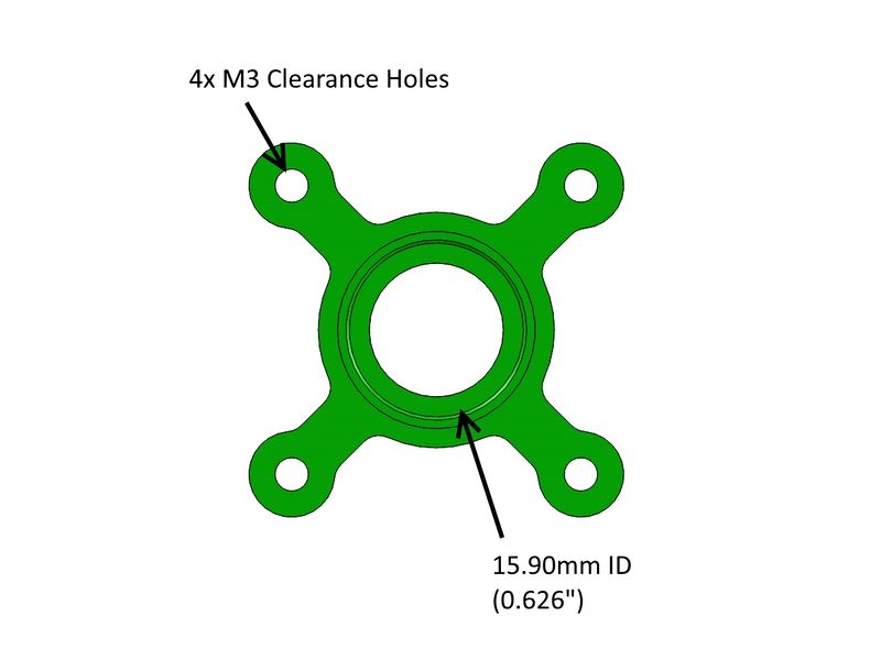
The assumption is your printer (or service) will hold the tolerance designed on an inside diameter. If your printer adds too much material you will need to make adjustments to accommodate the bearing OD which should push in with a little resistance:
|
Turret Base
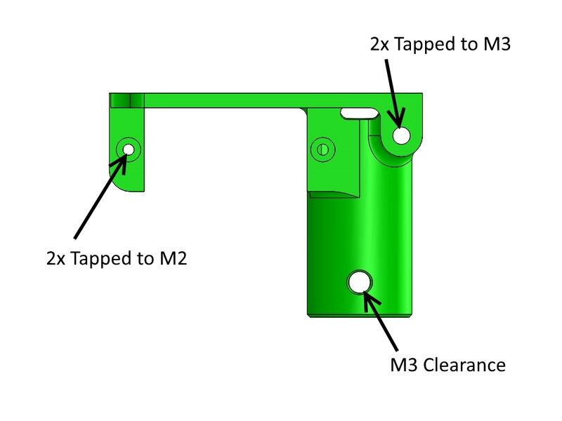
The Turret needs 2 holes tapped to M3 and 2 holes tapped to M2:
|
Servo Coupler
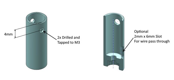
The Servo Coupler needs 2 holes drilled and tapped to M3:
|
Assembly
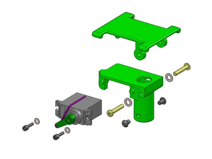
On the Camera Mount pivot use the two Nylon M3 screws cut down so that they tighten against each other without jamming the pivot points.
|
| Upper unit assembly |
|
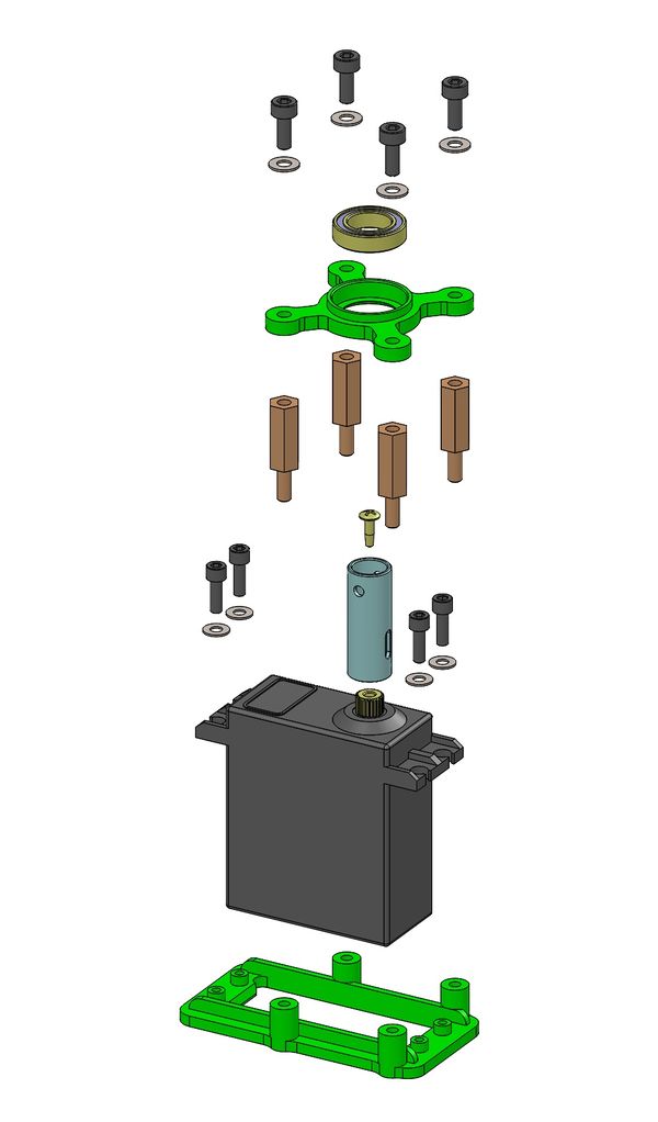
| Lower unit assembly |
See Also
Project 3D Print Files
The following are the 3D print ZIP files used in this specific build. For more versions and information, please see my Thingiverse postings here:
Mark_q Thingiverse Designs
Some of the Vendors I used for this project
Comments? Questions?