Difference between revisions of "Dynamic Motor and Prop Balancer"
| Line 8: | Line 8: | ||
|- | |- | ||
| | | | ||
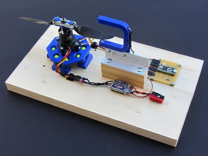
| − | | align="right" width="50%" | | + | | align="right" width="50%" | Balancer shown with an Aeronaut 8x7 folding prop |
|} | |} | ||
Revision as of 23:06, 2 November 2017
| |
This page or section is under construction and will change going forward.
Questions or Comments? Please contact the Wiki administrator |
© Mark Qvale - November, 2017
| |
| Balancer shown with an Aeronaut 8x7 folding prop |
Introduction
This project was actually done some years ago by some great posters on RCGroups and DoItYourselfDrones. Please see the Acknowledgements section at the bottom of this page. You can (& must!) read the original threads at these two links:
Basically, this is a dynamic balancer for motors and props that can be built for $60 or less. In the original write-ups there are two versions of the control board and firmware but this build only covers the version that uses the Teensy micro-controller.
My Build
This has been a very fun project for me having spent a large part of my life as a machinery designer.
My build here is but one of many versions you can find on RCGroups. I designed the cushion arrangement to more effectivly distribute the un-balanced load for a cleaner measure. I don't know if it actually works better than the four point cushion mounts others have built but it does work well.
The purchased components I have selected are the more expensive of the many different components mentioned but I felt they had the best guarantee of success. The 3D parts are all of my own design and have proven out well. I used ABS as a print material although PLA or PETG would also work just fine.
Parts
The purchased parts listed here are what I chose for this project. There are veriations of most of these you can see on the RCGroups thread. If you do choose different components, keep in mind your particular wiring may change and this information too can be found on the thread. The first five parts include links to where I bought them.
Purchase Parts
- Teensy USB Microcontroller, Version 3.2
- 3-Axis ADXL345 Digital Acceleration Module
- QEE123 - Plastic Infrared Light Emitting Diode
- QSE159 - Silicon Photosensor
- 300g Gimbal cushions
- 56 ohm 1/4 watt resistor
- 100 ohm 1/4 watt resistor
- 10K ohm 1/4 watt resistor
- Standard Red LED
- 50mm x 60mm Hobby Board
- Pin Headers
- M3 x 15mm Aluminum Stand-offs
Make Parts
The "make" parts listed below include three 3D printed parts, a simple flate piece motor mount, the control board and a wood base. You are certainly free to change any of this and there are many versions of all of these pieces found on the thread. The STL print files can be found near the bottom of this page under "3D Print Parts".
- Photo Sensor mount
- Cushion Bases
- Balance platform
- Motor mount plate
- Teensy control board
- Wood base
IR Photo-sensor Mount
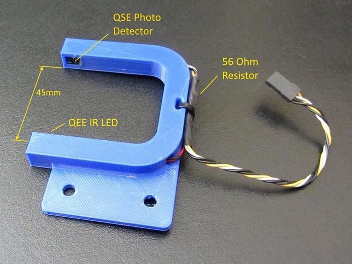
The photo sensor mount has a gap of 45mm for the blade to pass through which for the motor and prop sizes I have built it for works well. I mounted the IR detector on the top and the IR LED on the bottom so it wouldn't be susceptible to IR from ambient room light.
|
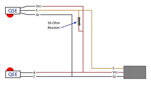
The wiring for this includes the 56 Ohm resistor in the wiring on the mount itself.
|
Cushion Base
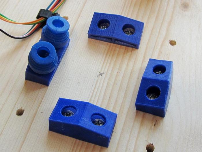
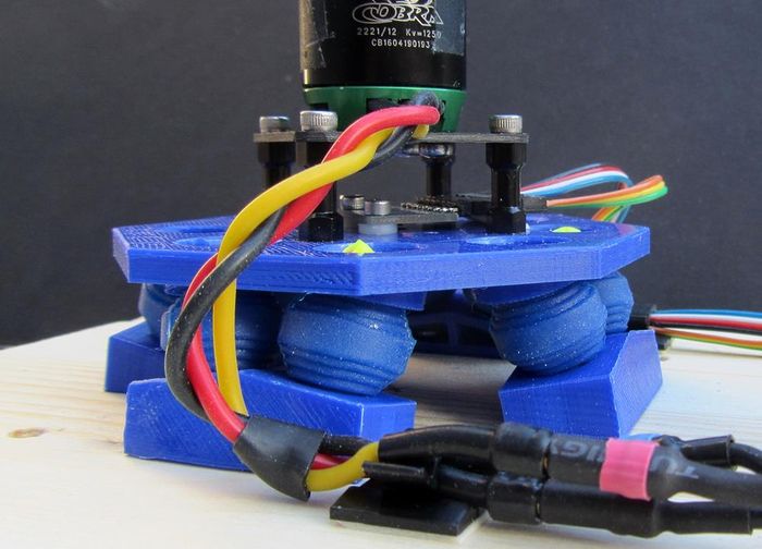
The Cushion Base is made up of four printed parts. Each cushion is leaning towards the center at an angle of 12 degrees and away from each other by 10 degrees. This helps to limit the effect of torque on this type of cushion arrangement and brings the tilt action more in line with the platform rotation.
|
Balance Platform
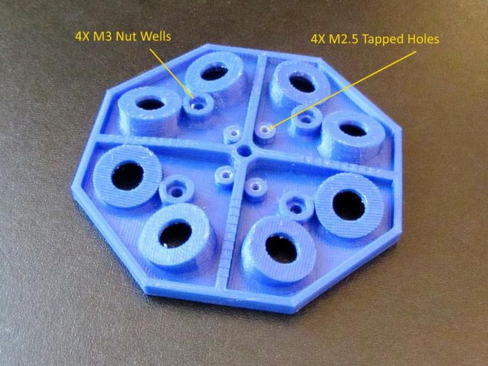
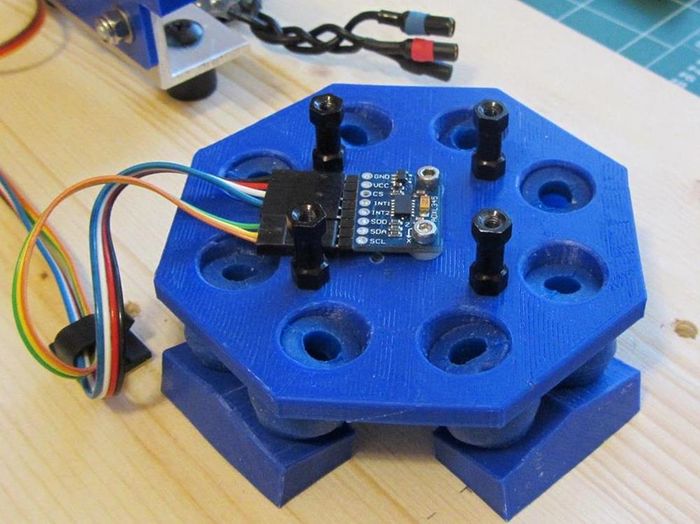
The balance platform is printed in ABS with support upside down. It has four "nut wells" for four M3 plain nuts and four holes tapped to M2.5 to hold either the Adafruit ADXL345 accelerometer or the ones found on Ebay (require slightly different wiring). The aluminum standoffs shown are M3 x 15mm but any size will do that clears the ADXL unit. You should put foam or servo tape under the ADXL to dampen high frequency vibration
|
|
|
Motor Plate
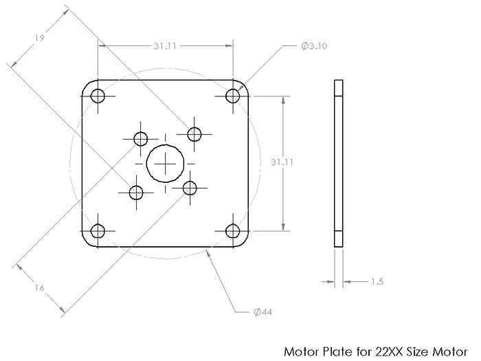
I made the motor plate out of a piece of 1.5mm Carbon Fiber. The bolt holes that attach to the stand-offs are on a 44mm circle which is the same as many 28xx size cross mounts. You could also use G10 fiberglass or even plywood for this providing it doesn't flex. I did not make this a printed part because there are so many different motor mount screw sizes and configurations.
|
Wiring
The wiring shown here is derived from several drawings on the thread. I added the LED indicator LED so you get a visual of when the prop crosses the beam. I also have the ADXL Vcc pin wired directly into the Vin terminal of the Teensy board (5v) which is different from other drawings you may fine but this has worked perfectly for me.
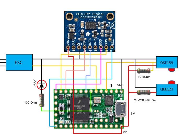
|
| The complete wiring diagram with Adafruit ADXL345 |
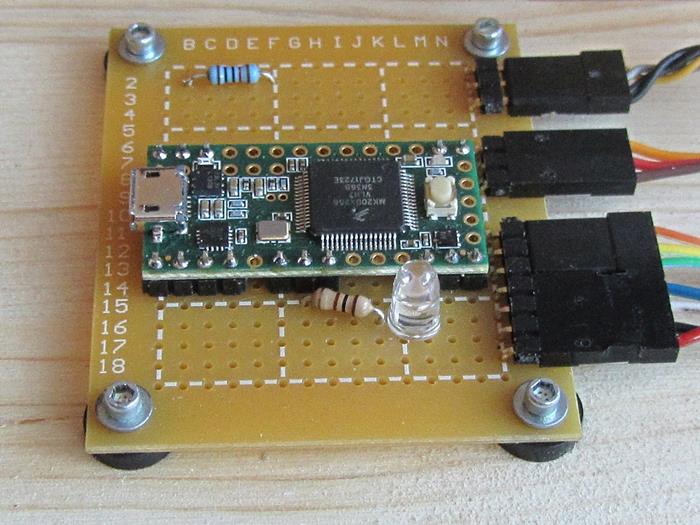
|
| My control board |
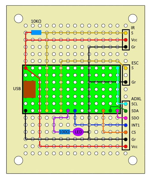
|
| My control board wiring (top view) |
Videos
The following excellent videos are provided by cyborgcnc:
Acknowledgements
Enormous thanks to the following folks who clearly spent a lot of time working to get this all working superbly!:
- Frank Al (diydrones 10/2012)
- The original creator of the DPB, initial softwares and first projects around this awesome, incredibly useful tool.
- cyborgcnc (RCGroups 01/2015)
- This poster has graciously supplied all the information I needed, firmware for the control board and extremely well done user interface for this project.
- adolfotregosa (RCGroups 03/2015)
- Provided great insight and help with development of the final software.
- lasakro (RCGroups 09/2015)
- Also provided lots of good insights and pictures of his work.
There are many more who contributed and are still developing but these four had the most influence on my particular build.
See Also
TBA